In this article, we are going to study the meaning of certain markings and the tests required to mark some of the most important parameters. To this end, and owing to the difference between different light sources, we will compare an LED driver (figures on the left) and a ballast to supply power to fluorescent tubes (figures on the right).
Manufacturer/Reference/Function:

All markings start with the name of the manufacturer, the reference assigned to the piece of equipment in question and its function. Aforementioned function is related to the type of light source that is capable of feeding the piece of equipment (LED modules, fluorescent lamps, HID lamps, etc.).
Wiring system:

This section indicates both the way in which the input to the piece of equipment must be connected to the mains, as well as the output from the equipment to the light source to be fed depending on the situation and orientation of the connecting terminals. It also indicates the proper way to connect the devices to adjust or dim the different lamps.
Electrical input parameters:

We have the nominal voltage (Un), the nominal frequency (fn) and the maximum acceptable alternating and direct current input values (AC/DC Input).
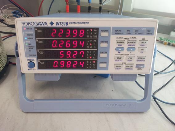
The input current range (In) and the power factor (λ) are also indicated. An instrument called a wattmeter that measures different input parameters is used to get both values.
The power factor is measured by connecting the nominal load of the equipment at the output and the input voltage at 230V, while to get extreme input current values you vary between maximum power with minimum input voltage (minimum In) level and minimum power with maximum input voltage (maximum In) level.

Wattmeter
Electrical output parameters:

This is the point where the difference between equipment designed to feed different light sources becomes more acute.
For drivers to feed LED modules, output current (Iout), power (Pout) and voltage (Vout) values, as well as the maximum no load output voltage (Vout max) are normally marked. Thus, it is possible to check both quickly and easily whether or not an LED module can be fed by a particular driver.
The type, power and number of lamps that can be connected at the output (we can see in the image that the sample piece of equipment can have 3 to 4, 18W lamps, of the T8 or TC-L type connected) are normally indicated for fluorescent lamp ballasts.
Temperature markings:

Two temperature parameters are indicated for lighting equipment, both of which are essential to its service life.
Firstly, we have the operating temperature range (ta), the minimum value of which determines the minimum temperatures accepted by the electronic parts that go to make up the equipment, without jeopardising its operation or features.
Secondly, it also indicates the maximum acceptable temperature at the measurement point marked on the enclosure so as to ensure proper equipment operation (tc). For temperature tests and to mark the corresponding tc, the equipment is placed in an environmental chamber, connected at maximum load and without any type of external ventilation. The temperature is then gradually increased and by means of thermocouples placed at the tc point and on the different components that determine the service life of the equipment (particularly all the electrolytic capacitors) the maximum operating temperature is obtained to ensure the service life given for the piece of equipment and the maximum acceptable temperature value at the tc point of the enclosure.

Environmental chamber
Other symbols of interest:

Safety Extra Low Voltage (SELV): A piece of equipment can be marked with SELV when the primary circuit is galvanically isolated (or if the only connection is by means of a Y1 capacitor) and the direct current between the output terminals is under 50V AC or 120V DC ( with a ripple never higher than 10%). At the same time, electric strength requirements between primary and secondary (3850Vac) must also be met and between them and the cover in case this one is metallic.

Device protected against overheating. The number inside the triangle indicates the maximum temperature at any point on the enclosure of the ballast or driver in the event of a fault or abnormal functioning of the equipment.

This indicates the degree of protection against the penetration of solid bodies and accidental contacts with live parts (first figure), against water penetration (second number) and against shocks (third number). The higher the number, the greater the degree of protection.

Adrián Garcés, R&D Department